




 English

Thin-wall CNC Machining lets fabricators make metal parts that're light, take up less space, and fit tight tolerances. These parts work well in industrial settings. But here’s the thing. Thin walls are very sensitive. They can. Warp under cutting force, machine vibration, clamping pressure, or leftover stress from machining. These issues make it hard to keep dimensions accurate and get a clean surface.
If you’re buying custom CNC machined parts, knowing the basics of thin-wall design can help. It cuts down on risks during production, keeps costs under control, and helps ensure you get the quality every time. This guide explains the problems you’ll face with thin-wall CNC Machining. It also gives tips for designing and making parts so you can reliably produce high-quality custom metal components.
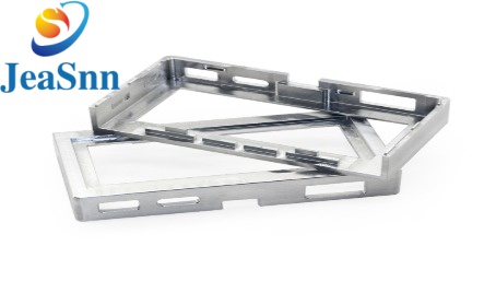
1. What Is Thin-Wall CNC Machining?
Thin-wall CNC machining is a way of cutting metal that creates parts with walls, small holes, ribs, and partitions using CNC milling or CNC turning. Compared to metal blocks, thin-walled parts are not very strong. When walled parts are cut or held tightly, they can bend and shake, which makes their size and shape less accurate and can result in a rough surface.
Thin-wall CNC machining is often used to make aluminum enclosures, lightweight brackets, precision panels, thin sleeves, electronic housings, and parts for aerospace and automotive use. Aluminum alloys are chosen for their strength and easy cutting. Stainless steel and other alloys are chosen when stronger, corrosion-resistant, or more wear-resistant parts are needed.
The smallest wall thickness that can be made depends on the Material, the height of the wall, the shape, the tools, the way the part is held, and the tolerance limits. There is no rule that applies to all cases. A short, supported thin wall is easier to cut than one with the same thickness, so the whole design should be looked at carefully.
2. Why Is Thin-Wall CNC Machining Challenging?
Thin-wall CNC machining comes with a set of linked problems that require careful process control. The first common issue is wall deflection. When cutting tools apply pressure, thin feature walls bend away from the cutter and change the actual cutting conditions. Take custom aluminum housings with cavities and narrow dividers as an example: walls are strong at the start but lose strength once surrounding material is removed. This leads to uneven wall thickness, out-of-spec dimensions, distorted shapes, poor surface quality, and more scrap. To reduce deflection, machinists use shallow cutting passes, better toolpaths and sharp cutters with support. Designers should also avoid making walls too tall and unsupported if possible.
Next, low strength causes vibration and noise. Unwanted shaking leaves marks, textures, and speeds up tool wear, which can damage later steps like anodizing and polishing. Much tool force, long thin cutters, and poor holding tools increase this risk. Operators need to adjust the spinning speed, feed rate and cut depth based on the material and shape. Short, strong tools and good holding tools are better; just increasing the spinning speed does not always work.
Third, wrong holding causes bending. Much holding force can bend thin rings, aluminum sheets, and brackets. A thin ring might become oval in a chuck and change shape when released. Parts might pass size checks while being held but fail when let go. Soft jaws, matched supports and spread-out holding setups help hold parts without changing their shape. The holding tool design must match the machining steps to stay stable.
Fourth, leftover stress causes bending. Raw metals have stress from rolling, pulling, or heating. Removing material breaks the stress balance, and thin walls or big pockets are very likely to bend, especially for aluminum parts with deep cavities and uneven material removal. The bending might happen during machining or after letting go. Balanced material removal and proper roughing and finishing steps. Stress relief can be added if it works with the material and needs.
Finally, heat from cutting harms the surface and size. Thin parts don’t hold heat and can’t cool down fast. Even though aluminum conducts heat well, stainless steel and other materials are harder. Much heat, blocked chips, and wrong cutters cause surface problems. Right cutters, settings, good chip removal, and coolant use are important. Critical parts should be checked only after they cool down.
3. Thin-Wall CNC Machining Design Tips
Design for Manufacturability (DFM) is a way to improve thin-wall machining results. Checking wall shape before making parts saves time and lowers tooling complexity. Makes sizes more consistent.
3.1 Choose a Wall Thickness
The smallest workable thickness changes based on the material type, unsupported height, part size, shape, machining steps, and size goals. No single thickness works for everything. Designers should use walls if possible to avoid making parts too thin and check thickness with wall height and free space. Holding support and cutter access also need to be thought about early, and very thin parts should be talked about with the maker first. If thin parts are needed, an engineering check helps see if CNC Milling, turning, sheet metal, or other methods are best. The main aim is to balance weight, strength, making it, and cost of just trying to make things as thin as possible at the cost of making them correctly.
3.2 Keep Wall Thickness the Same
Sudden changes in wall thickness make it hard to cut properly. For example, cases with parts and thin walls next to them behave in a way that is hard to predict as material is taken away, causing bending risks because of different strength and stress. Smooth, gradual changes are better when possible to make tool paths easier and reduce finishing work. Still, the real needs come first; parts that hold things have threads. Bearings need more material to handle the weight.
3.3 Add Stronger Ribs and Supports
Ribs and supports make things stronger without making the wall thicker. Placed smartly on custom cases and brackets, they stop shaking and bending during cutting and when in use. When designing these parts, think about forces, cutter reach, inner curves, chip movement and how things fit. Rib designs should avoid corners that're hard to cut. Extra supports can be. Cut away in the end depending on the shape and what can be done.
3.4 Choose Good Inner Corner Sizes
Standard cutters can’t make sharp inside corners directly. Small corner sizes need less strong cutters that go slower, making the time longer and more chance of shaking for thin walls. Set corner sizes that match tool sizes; if sharp corners are needed, relief cuts can be used, but check if they fit and leave enough space.
3.5 Don’t Make Deep Narrow Pockets
Deep narrow holes are hard to cut and make it hard to remove chips. Walls in these pockets get weaker as they are cut. Make the holes wider, cut deep, and leave enough room for the cutter. Early checks for aluminum cases find parts that need special tools or more finishing.
3.6 Only Use Tight Tolerances Where Needed
Tight sizes make the time longer, check more, and cost more. Thin parts move easily when held or let go. Engineers should see which sizes are important and which are not on the drawings. For a case, the places where holes are and where seals go need sizes, while the outside that looks good can be looser. This lets the cutter focus on the parts and helps with pricing, for special tools and exact steps.
4. Manufacturing Solutions for Better Thin-Wall CNC Machining Results
Well-executed DFM design lays the groundwork, yet a refined machining strategy is the deciding factor for stable, repeatable thin-wall component production.
4.1 Adopt Segmented Roughing and Finishing Routines
Bulk material removal in a single pass generates heavy cutting loads and leaves delicate thin structures prone to deformation. A phased machining workflow works better. Roughing clears most stock while retaining enough residual material for structural backing, with a uniform finishing margin reserved on key walls. Balanced stock removal on opposite sides is recommended where geometry permits, alongside pause periods for thermal and stress stabilization before final cuts. Light finishing passes then deliver target dimensions and surface finish. The workflow adjusts for different materials and shapes; intermediate checks or stress-relief steps between roughing and finishing are helpful for challenging parts. This approach prevents thin, unstable walls from forming prematurely.
4.2 Optimize Cutting Tools and Toolpath Programming
Your cutter selection plays a big role in cutting forces, chatter, and consistent dimensional results. For thin-wall milling, use rigid tools with efficient chip evacuation and cutting edges optimized for your material. Plan your toolpaths to prevent excessive cutter contact and sudden load shifts. Adaptive milling, reduced radial engagement, and well-organized finishing passes help maintain stable machining conditions. The optimal combination is tailored to wall geometry, alloy grade, machine capability, and tolerance specifications for custom machined workpieces.
4.3 Upgrade Workholding and Fixture Support
Conventional clamping approaches struggle to secure thin-wall parts reliably, but application-tailored fixturing delivers dependable support. You may opt for contoured soft jaws, custom base plates, internal support inserts, vacuum chucks for flat thin workpieces, or sacrificial support features. For thin cylindrical components, evenly distributed contact surfaces reduce deformation during turning and follow-up secondary operations. Fixture development should also take into account tool access, positioning repeatability, and part loading arrangements synchronized with the machining sequence.
4.4 Choose the Appropriate CNC Machining Method
Milling and turning serve distinct feature types. CNC milling fits thin enclosures, cavities, brackets, and irregular profiles, whereas turning is ideal for rotary parts such as thin sleeves and rings. Mill-turn operations suit components mixing rotational and milled features. Multi-axis machining can simplify tool access and cut setup counts for intricate designs, though advanced equipment is not always the best fit. An experienced CNC supplier evaluates each part’s geometry to propose a process balancing precision, throughput, and overall cost.
5. Custom Thin-Wall CNC Machining Services for Your Project
Selecting a competent manufacturer is critical for thin-wall CNC machined components. Your supplier needs solid expertise in the interplay of part geometry, material characteristics, workholding setup, cutting loads, and dimensional verification.
At CNCPartschina.com, we invite clients to submit full technical documentation for a manufacturability assessment prior to production. We produce bespoke aluminum housings, precision support brackets, thin-walled sleeves, lightweight structural components, and a full range of custom CNC metal parts. Our in-depth technical review identifies manufacturability risks well ahead of formal production.
For precise quoting, kindly share 2D drawings, 3D CAD models, material specifications, key wall measurements, GD&T requirements, surface texture and plating needs, order quantities, inspection criteria and target lead times. Mark ultra-thin sections and intricate internal geometry clearly within your RFQ. This lets our engineering team evaluate suitable cutting tools, custom fixturing, machining sequences and inspection protocols.
Email:engineer@cncpartschina.com
Send your drawings and project specifications to CNCPartschina.com. We will prepare a formal quotation and develop a customized manufacturing plan for your parts.